The choice between line-scan imaging and structured-light 3D measurement is one of the most consequential hardware decisions in an automotive inspection cell design — and the two technologies are more complementary than they are competing. Line-scan cameras and structured-light 3D sensors answer different questions about the same part. Understanding what each modality measures, where it excels, and where it has practical limits is the foundation for specifying the right sensor for a given inspection requirement.
This guide covers the technical differentiators across the key evaluation axes quality engineers use when selecting sensors: surface coverage, depth measurement capability, cycle time behavior, calibration complexity, and part geometry suitability. We will also discuss where time-of-flight (ToF) depth sensors sit relative to structured light for specific automotive applications.
How Line-Scan Imaging Works and What It Captures
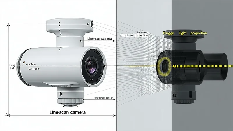
A line-scan camera captures a single line of pixels at a time — typically a 1 × N pixel array where N may be 2048, 4096, or 8192 pixels wide. As the part or camera moves relative to each other, successive lines are stitched together to build a 2D image of the part surface. The result is a high-resolution 2D reflectance image — the same type of data that an area-scan camera produces, but built from continuous motion rather than a snapshot.
The key advantage of line-scan over area-scan for large or long parts is resolution economics: a single 8K line-scan camera images a continuous strip at 8192 pixels across, enabling sub-0.05mm pixel pitch over a wide web. An area-scan camera achieving the same ground sampling distance over a 400mm × 300mm part would require a 60MP+ sensor — expensive, slower to transfer, and constrained by frame rate limitations that line-scan naturally avoids because only one row is read per clock cycle.
Line-scan imaging captures 2D surface reflectance. It does not directly measure depth or height. For surface defect inspection (scratches, voids, contamination, coating uniformity), line-scan provides exceptional resolution and throughput. For geometric form measurement (flatness, profile, height variation), line-scan alone is insufficient — it shows where the surface is light or dark, not where it is high or low.
How Structured-Light 3D Works and What It Captures
Structured-light 3D sensors project a pattern — typically sinusoidal fringes or binary-coded stripes — onto the part surface. A camera positioned at an angle to the projector captures the deformed pattern. Using triangulation geometry, the system reconstructs a 3D point cloud representing the surface height at each point in the field of view.
The primary output is a depth map or point cloud — every point in the field of view has an X, Y, and Z coordinate. From this data, GD&T characteristics can be computed: flatness (maximum deviation of surface points from a best-fit plane), profile of a surface (deviation from nominal CAD), step heights, weld bead cross-section geometry (width, height, undercut depth).
Structured light does not inherently provide the high-resolution 2D reflectance image that line-scan produces. The point cloud density is determined by the fringe pitch and camera resolution — typically 0.05–0.5mm point spacing for automotive-range sensors, compared to line-scan's potential for 0.01–0.05mm pixel pitch for surface defect detection. For this reason, systems requiring both high-resolution surface defect detection and accurate 3D form measurement typically combine line-scan for 2D and structured light (or laser line triangulation) for 3D — either as separate stations or integrated into a single sensor housing.
Cycle Time Behavior: The Part Motion Constraint
This is where the two technologies diverge most significantly in a production line context.
Line-scan is designed for parts in continuous motion. The camera reads one line per encoder pulse — as the part moves, the image builds naturally. There is no requirement to stop the part; in fact, stopping a part under a line-scan camera stops image acquisition entirely. Line-scan inspection is inherently compatible with conveyor-fed production lines. Inspection cycle time is determined by how long the part takes to pass through the scan field at production conveyor speed — typically 0.5–2 seconds for automotive parts on standard conveyor speeds of 200–500mm/s.
Structured-light 3D (multi-shot phase shifting) requires the part to be stationary during pattern projection and capture. A standard multi-shot measurement cycle projects 4–12 phase-shifted fringe patterns, capturing a camera frame for each — typical measurement cycle times of 200–1000ms. This requires an indexing stop-and-measure station where the part is halted, measured, and released. The cycle time impact must be designed into the line during APQP Phase 2.
Single-shot structured-light systems (capturing all depth information in a single exposure using color multiplexing or advanced coding) reduce this to 20–100ms and can operate on slow-moving parts — but sacrifice depth resolution and point density compared to multi-shot approaches.
Laser line triangulation (a specific structured-light variant using a laser line instead of fringe patterns) is compatible with continuous motion: the laser line illuminates a cross-section of the part as it moves, and the camera captures the distorted line profile. Multiple profiles are stacked to build a 3D surface map — the same principle as line-scan, but measuring height rather than reflectance. Laser line triangulation is commonly used for weld bead inspection on continuously welded parts moving through a welding cell, where multi-shot structured light cannot be used.
Calibration Complexity Comparison
Line-scan calibration for dimensional measurement requires: a flat-field calibration to correct for illumination non-uniformity across the scan line, a geometric calibration using a precision reference ruler or target to convert pixel coordinates to physical dimensions, and an encoder calibration to ensure the pixel pitch in the scan direction matches the physical distance the part travels per encoder pulse. For a well-designed installation, this calibration is stable for extended periods between calibration intervals and can be performed in under 30 minutes by a trained technician.
Structured-light 3D calibration is more involved: it requires a 3D calibration artifact (typically a precision planar or spherical reference) imaged at multiple orientations to establish the camera-projector geometry, correct for lens distortion, and establish the Z-axis scale. Calibration is sensitive to temperature changes that affect the geometry of the sensor housing — industrial-grade structured-light sensors incorporate thermal compensation, but field calibration verification at production startup is good practice. Full calibration of a structured-light system typically takes 1–3 hours and requires the calibration artifact traceable to NIST.
Neither technology is difficult to calibrate by a qualified vision engineer — but structured light has more calibration parameters and more calibration failure modes that a commissioning team needs to understand.
Part Geometry Suitability
Line-scan is well suited to: flat or near-flat parts that traverse continuously, long parts or continuous webs (coils, extrusions, belting) where the part length exceeds what any area-scan camera can image in a single frame, and surfaces where high-resolution 2D texture analysis is the primary requirement. Challenging cases for line-scan: highly curved parts that present varying distances to the lens as they travel (focus variation, perspective distortion), parts with complex 3D features that require height information, and parts that cannot be transported at controlled speed on a conveyor (irregular or fragile parts handled by robot).
Structured-light 3D is well suited to: parts with significant 3D form (castings, forgings, housings with complex topology), weld beads and formed joints where height profile is the primary measurement, and batch inspection where parts can be placed on an indexing fixture. Challenging cases for structured light: highly reflective surfaces that saturate the fringe pattern (polished stainless steel, chrome plating) — though polarized illumination and specialized fringe coding partially mitigate this; very dark surfaces (matte black coatings) that absorb the projected pattern; and applications requiring simultaneous high-resolution 2D and 3D on the same surface.
Time-of-Flight Depth Sensors: Where They Fit
ToF sensors measure depth by timing the round-trip travel of pulsed or modulated light. They produce 3D point clouds at video frame rates (30–100fps) without requiring pattern projection or part stillness. For automotive inspection, ToF sensors are typically suited to: robot guidance applications where rough 3D presence and position is needed rather than precision measurement, part-in-fixture verification, and bin picking.
We are not saying ToF depth sensors are unsuitable for any precision measurement. But their depth resolution is generally 0.5–5mm for production-cost-range sensors — an order of magnitude coarser than phase-shifting structured light at 0.05–0.1mm. For GD&T characteristics with tolerances below 1mm flatness or profile, ToF sensors do not meet the measurement uncertainty requirement. For coarser presence/absence and gross geometry checks on large assemblies, they are appropriate and economical.
Practical Selector: Which Sensor for Which Application
| Application | Primary sensor | Rationale |
|---|---|---|
| Powder coat void / scratch detection on flat panels | Line-scan (2D) | Continuous motion, high resolution needed, no depth measurement required |
| Weld bead geometry (width, height, undercut) | Laser line triangulation or multi-shot structured light | Height profile is the primary measurement; compatible with conveyor or indexing |
| Flatness of stamped metal panel | Structured light 3D (multi-shot, indexing stop) | 3D depth map required; tolerance typically 0.3–1mm, within structured light capability |
| Machined bore diameter and position | Area-scan 2D (sub-pixel edge) | 2D measurement from calibrated field; line-scan not needed for discrete features |
| Large casting profile (100–400mm field) | Structured light 3D | Complex 3D topology; area-scan 2D insufficient for profile measurement |
| Coil or roll coating uniformity (web inspection) | Line-scan (2D, color) | Continuous web, width exceeds area-scan capability at required resolution |
The most effective inspection cells for complex automotive parts often combine sensor modalities: a line-scan pass for surface defect detection at high resolution, followed by a laser line triangulation or structured-light 3D measurement for critical form characteristics. The two measurements can be performed at the same station (sequentially or simultaneously with different illumination channels) or at adjacent stations in the inspection sequence.
Sensor selection should be documented in the process design phase of APQP — before capital is committed and fixturing is designed. Retrofitting a structured-light stop-and-measure station into a line designed for continuous-motion inspection is a significant redesign; the time to identify the right modality is during process FMEA, not during PPAP.
If you are at the process design stage for a new inspection cell and need a technical review of which sensor modality matches your part geometry and defect detection requirements, contact the Qcvisionly engineering team for an assessment.