Most teams start with a pretrained model off the shelf. It works in the demo. It detects scratches on the sample parts. Then they put it on the line and false-positive rates hit 12%, and operators start ignoring alerts. Here's the thing: generic models were trained on publicly available defect datasets that look nothing like your stamped aluminum bracket or your chrome-plated trim strip. The model never learned your part geometry, your surface finish, your specific defect morphology. That gap costs real money. We've seen manufacturers spend six months on a deployment that should have taken two, because nobody budgeted for fine-tuning.
This article covers what a real fine-tuning process looks like when you're working with Basler industrial cameras, from camera selection through the training cycle to the ongoing recalibration schedule that prevents model drift as tooling wears.
Why Generic Pretrained Models Miss Fine Surface Defects
The core issue is domain shift. A model trained on MVTec or similar open datasets has learned to detect scratches, dents, and contamination under controlled lighting on generic surfaces. Your actual production environment introduces variables that break those learned representations fast.
Surface reflectance is the first problem. Automotive-grade stamped steel with a mill finish has a specular reflection profile that bears almost no resemblance to the matte surfaces in standard defect benchmarks. A 0.3 mm scratch on a mirror-polished surface generates a completely different intensity gradient than the same scratch depth on a brushed finish. Generic models don't know the difference. They were never shown it.
The second problem is defect class imbalance specific to your process. Your stamping die produces a very specific family of edge burrs. Your welding fixture leaves a particular heat-affected zone pattern. These process-specific defect signatures are rare in open datasets. Without fine-tuning, you're asking the model to generalize from loosely similar examples, and the results show it.
In our tracking of initial deployment accuracy across multiple fine-tuning projects, generic pretrained models running on production automotive parts typically achieve 73-81% recall on fine surface defects before any domain adaptation. That means roughly 1 in 5 real defects is missed. Not acceptable for a tier-1 supplier under IATF 16949 with a customer-mandated PPM target.
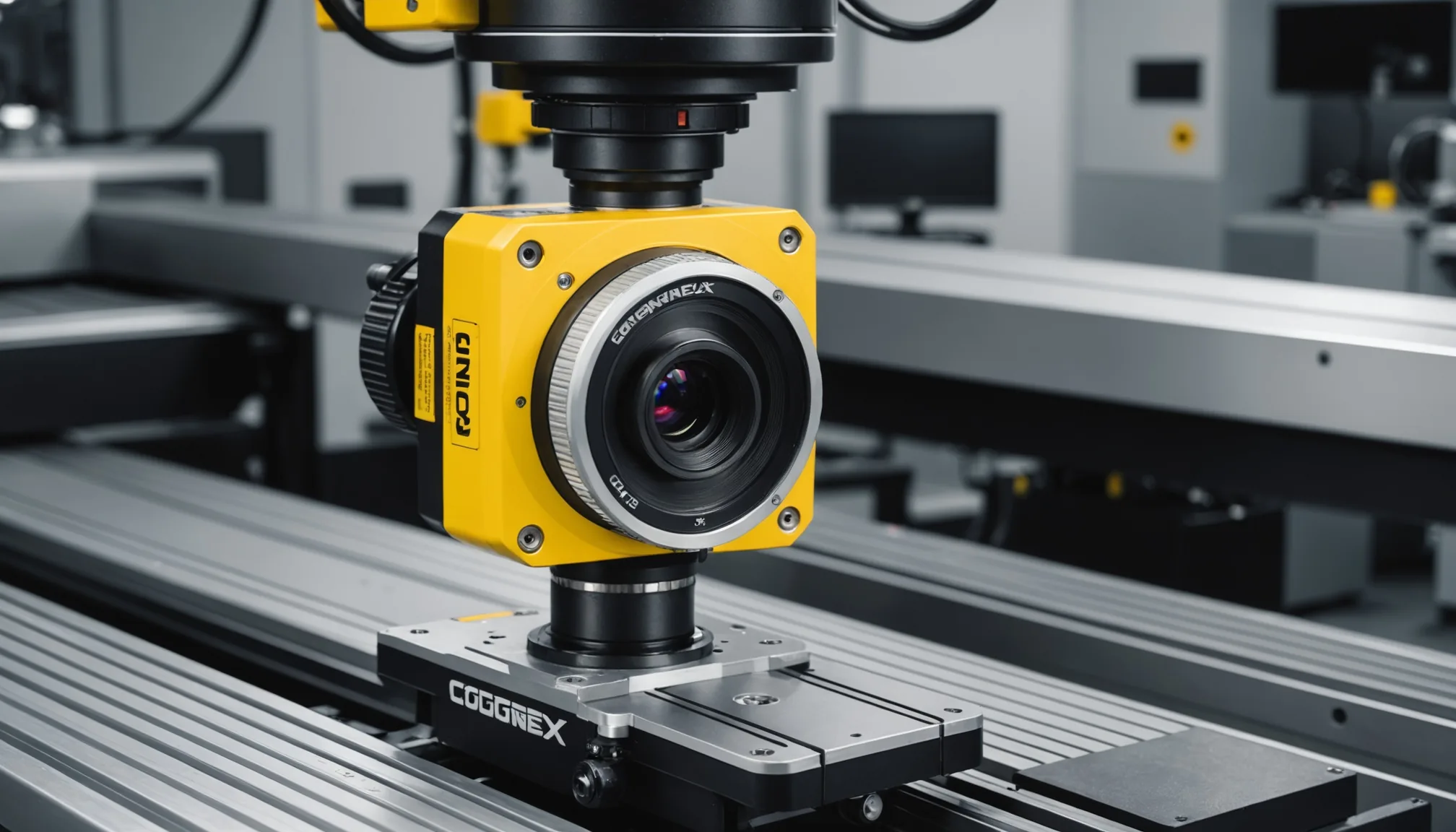
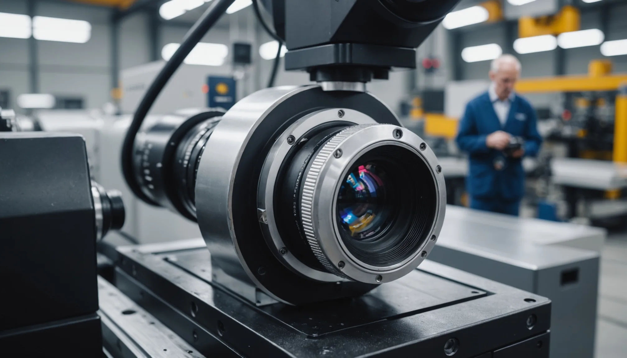
Basler Camera Selection for Defect Detection
Camera selection dictates everything downstream. Get this wrong and no amount of model fine-tuning will save you.
For fine surface defect inspection on automotive parts, the Basler ace 2 series is the platform we work with most frequently. The key specifications to pin down before purchasing:
| Parameter | Requirement | Why It Matters |
|---|---|---|
| Resolution | 12 MP minimum for parts >200 mm | Smaller defects need pixel budget at working distance |
| Frame rate | Match line speed with 20% headroom | Buffer for burst intervals and exposure compensation |
| Sensor type | GS (non-rolling shutter) sensor | Eliminates motion artifact on moving conveyors |
| Interface | GigE Vision or USB3 Vision | Latency consistency for inline triggering |
| Lens mount | C-mount with locking collar | Prevents focal plane drift from vibration |
Lens selection matters almost as much as the sensor. For most automotive surface inspection tasks, a fixed focal length lens in the 25-50 mm range outperforms zoom lenses on consistency. Zoom mechanisms introduce backlash and focal plane shift. Fixed lenses hold calibration. For very fine surface defects below 0.1 mm, a telecentric lens is worth the cost premium; it eliminates perspective distortion at the edges of field that creates false positives near part boundaries.
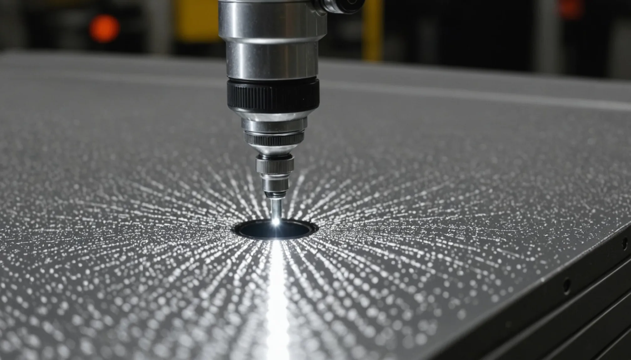
How Lighting Setup Affects Model Accuracy
This is the variable that most teams underinvest in, and it has the largest single impact on model accuracy. Fact: in our experience, poor lighting setup degrades a well-tuned model more than using a generic pretrained baseline with good lighting.
The relationship between lighting angle, surface finish, and defect visibility is not intuitive. A scratch oriented perpendicular to the light source will appear as a high-contrast edge. Rotate the part 45 degrees and the same scratch may nearly disappear. This means your lighting design needs to be engineered for your specific defect types and your dominant part orientations on the line.
Coaxial (on-axis) illumination works well for flat, specular surfaces where you want to detect disruptions in the reflection. Dark-field illumination, where the light comes in at a shallow angle, is better for surface topology defects like dents, pits, and raised burrs. Many production lines need both, triggered alternately to capture complementary information.
The fine-tuning dataset must be captured under production lighting conditions. Not lab conditions. Not prototype rig conditions. If you fine-tune on images taken under one lighting setup and then change the production fixture, your model accuracy will drop significantly until you retrain. We recommend locking down the lighting rig completely before image collection begins and treating any subsequent lighting change as a retraining trigger event.
The 6-Week Fine-Tuning Process
Here is how a realistic fine-tuning engagement runs. Six weeks is achievable for a single part family. Multi-part programs take longer.
Weeks 1-2: Data collection. The camera system runs on the production line in parallel with existing QC. Every reject gets photographed. Every borderline case gets flagged. You want a minimum of 500 confirmed defect examples per defect class you intend to detect. For rare defect types, this can take longer than two weeks. Do not skip ahead. Insufficient training data is the number one cause of fine-tuning failure we've seen.
Week 3: Labeling. Ground-truth annotation of the collected images. This step requires your quality engineers, not just data labelers. The distinction between an acceptable tool mark and a rejectable scratch is encoded in your internal quality standards, and that knowledge has to transfer to the bounding box or segmentation mask. Honestly, labeling quality determines model quality more directly than algorithm choice.
Week 4: Training and initial validation. Fine-tuning runs against the annotated dataset. Initial validation on a held-out test set, checking recall and precision across each defect class separately. Not overall accuracy. Class-level metrics. An overall accuracy of 94% can hide a recall of 61% on your rarest but most critical defect type.
Week 5: Shadow mode testing. The fine-tuned model runs on the line alongside your existing QC process. Every discrepancy between model output and human judgment is logged and reviewed. This phase typically surfaces 2-4 edge cases per defect class that were not represented in the training set. Those cases feed back into the annotation set.
Week 6: Retraining and acceptance testing. Incorporate the edge cases, retrain, validate. Run formal acceptance testing against a fixed test set with known ground truth. Pass/fail criteria should be defined before training starts, not after you see the results.
The Quarterly Recalibration Cycle
Fine-tuning is not a one-time event. Tooling wears. Dies accumulate microfractures that change part surface topology. Lubricant formulations change. A model that was performing at 96% recall in January may be at 88% recall come spring, not because the model degraded but because the production process drifted away from the training distribution. Simple as that.
We structure quarterly recalibration cycles into every deployment. The process:
- Pull a stratified sample of production images from the past 90 days.
- Re-annotate a random subset with current quality engineer review.
- Compare model predictions on this sample to annotations. Calculate per-class recall delta versus baseline.
- If any defect class has dropped more than 3 percentage points, trigger retraining.
- Retraining uses the original dataset plus the new sample. Never replace the original data entirely.
This cycle also catches camera system drift. Lens contamination, focal plane shift from thermal cycling, LED aging in the light fixture. All of these degrade image quality in ways that impact model inputs before the model ever runs. The recalibration process includes a camera health check: flat-field uniformity test, resolution target check, and lighting intensity measurement against the baseline values recorded at deployment.
In our data from deployed systems running through multiple recalibration cycles, the average recall drop without recalibration at the 6-month mark is 7-9 percentage points. With quarterly recalibration, that drops to under 2 points. The maintenance cost of recalibration is well below the cost of a quality escape.
Putting It Together
Fine-tuning a defect detection model on your Basler camera hardware is not a software problem. It is a production process problem that requires input from quality engineering, manufacturing, and the vision system team working together. The camera spec, the lighting design, the data collection discipline, and the recalibration schedule are all load-bearing. Skip any one of them and the model performance suffers in ways that are hard to diagnose later.
The six-week timeline is realistic for a well-scoped single part family with adequate QC staffing for annotation. The quarterly recalibration cycle is non-negotiable if you want to hold your accuracy targets as the production process changes over time. Get both right and you have a system that holds up under the scrutiny of a tier-1 customer audit. That's the goal.